Physical Ethernet Links TCs

Physical Ethernet Link TCs will be imported and provide logical connectivity between physical ports. TCs will terminate on Inner Ports allowing users to model the transport layer or physical network independently as a Main Bearer. Users will need to manually route the LLDP TC over the Main Bearer as this relationship is not available.
Physical Ethernet Link TCs are discovered by LLDP. Links can also be added manually in SAM but don’t seem to be available in the SAM-O Interface.
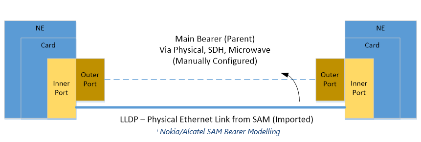
TCs will nominally be imported as 0GigE capacity and will need to be re-defined by the user if necessary based on limitations of the Main Bearer. i.e Main Bearer might be 155Mbs STM-1 Link and as a result the Bearer TC will need to be modified appropriately
Note: In this case M000020 will be imported from Nokia/Alcatel SAM on Inner Ports. User will then have to manually route over the Main Bearer elements as depicted
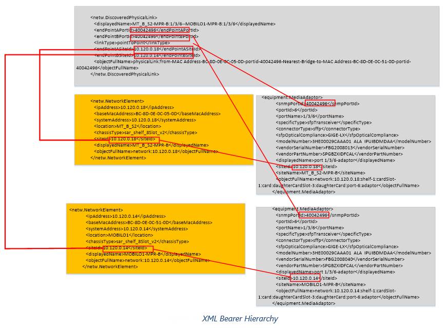
In order to process physical ethernet links the following files will be processed:
•netw.DiscoveredPhysicalLink.xml (Primary Data Source for the Bearer TC)
•equipment.MediaAdaptor.xml (Provides Mapping for PortID to Physical Port)
•netw.NetworkElement.xml (Provides Mapping for SiteID to NE)
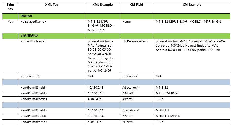
Field Mappings for Ethernet Physcal Links
NOTES:
1)TC Name will be considered unique
2)Location and Mux need to be resolved from netw.NetworkElement.xml based on <endPointXSiteId>
3)Port Name at each end to be resolved from equipment.MediaAdaptor.xml and netw.NetworkElement.xml where:
a.< endPointAPortId>=<snmpPortId>
b.<endPointXSiteId>=Location & Mux
c.PortId is not unique and needs to be combined with the MacAddress to find which NE the port sites under
4)TC have no imported routing segements these will be done manually by the customer as needed
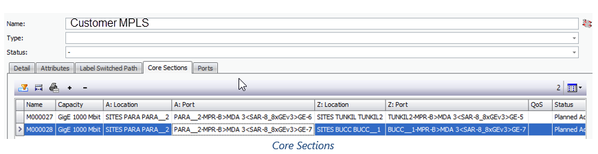
Mapping to MPLS Network – Core Sections
In order for MPLS logic to work in Connect Master, physical links must be added to a pre-defined MPLS Network.
TC will be added to the MPLS Core defined in XML config file if both end ports are Type = MPLS Network.
XML Bearer Hierarchy
Physical Ethernet Links TCs – Link Aggregation
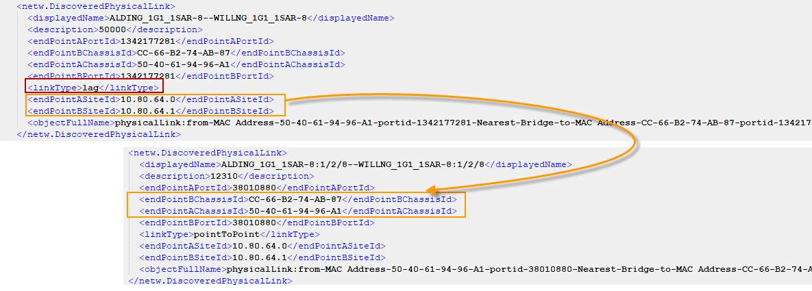
Link Aggregation will be imported as part of Physical Ethernet Links. LAG ports will be imported into ConnectMaster as virtual subports (refer to section Logical Ports and VLANs). LAG paths will be termnicated on these LAG ports and will be created as type LAG Path insated of Untilazable Containers in ConnectMaster. Link Aggriation will be created and assosiated with the LAP Paths with ConnectMaster type Link Aggregation.
XML Bearer Hierarchy for LAG
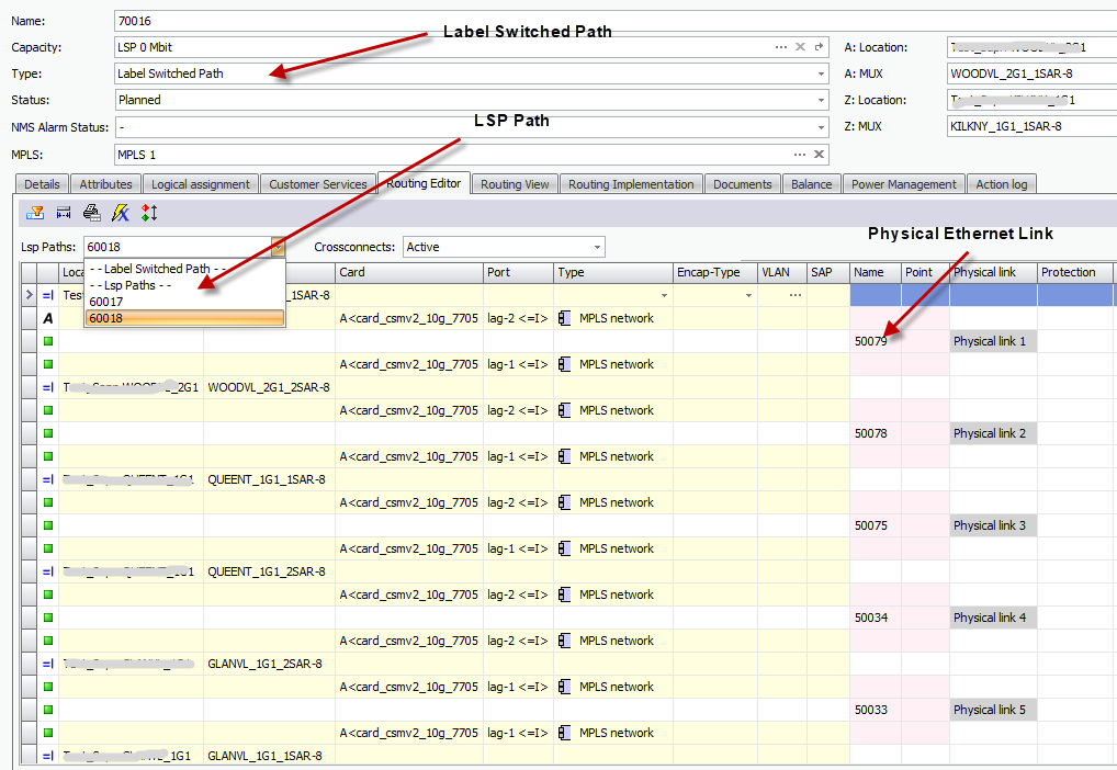
LSP TCs
LSP TCs will be imported and provide logical connectivity at the MPLS layer.
SAM Modelling
On the Nokia/Alcatel Routers and in SAM the general LSP hierarchy is as follows:
LSP -> LSP Path -> MPLS Tunnel -> Provisioned Path -> Hops
ConncetMaster Modelling
In CM SAM LSP will be mapped to a CM LSP. The LSP Object is defined with A and Z end Mux.
Strict and Loose LSP Paths will be created under each LSP containing hop/routing information.
Note that ENET does not currently have any strict backup LSP Paths. As a result impact analysis will only take into account the effect on the Primary strict path. In addition LSP Paths will not have a populated A and Z port as this would result in a port clash with the LLDP links already on the inner ports of MPLS trunk ports.
Bi-Directional and LSP Path Routing
Since each LSP and LSP Path is uni-directional on SAM they will need to be joined into bi-directional TC using the following rules/criteria:
•LSP Name and End Device A->B should have a matching B->A LSP
•For each LSP A->B and B->A use the custom attribute SiteId when matching IP to a NE
•Each Provisioned Path A->B and B->A should have same number of hops, intermediate elements and Type (ie Primary or Standby)
•When routing the LSP to the next intermediate NE, use the first TC that connect the two NEs defined by the Hop that terminates on inner-ports (this is based on current Bearer TC Logic Section 6.1)
Important! Since SAM is not able to provide information on which port exactly a LSP will exit a NE, CM will use the first valid TC. If the situation arises in the future where nxLinks have been configured between NEs additional logic might be needed to handle LAG architecture.
Valid TC between two mux will be filtered using the ReferenceKey field populated for LLDP links during synchronisation process. Valid TC will have ReferenceKey <> Null indicating that they match SAM.
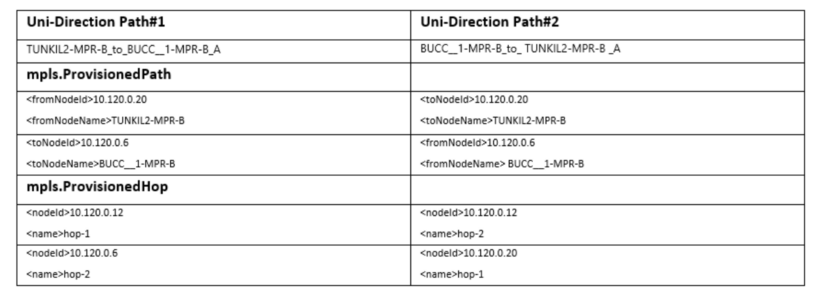
Sample Uni-Direction Routing Data for LSP Path (XML Data)
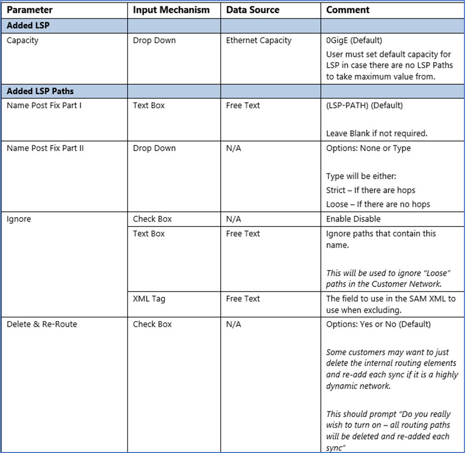
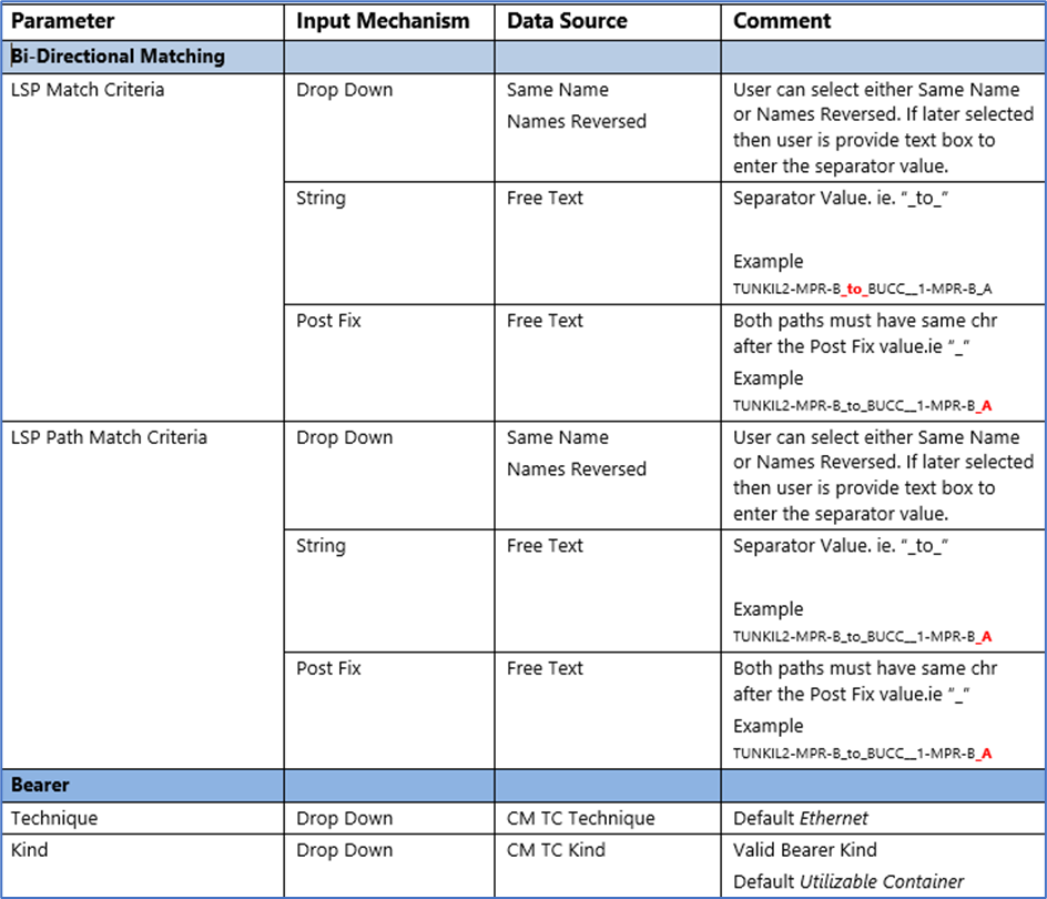
Configuration Parameters
Field Mappings
Source File – mpls.DynamicLsp.xml (Initial Data Source for LSP)
Source File – mpls.LspPath.xml (Provide reference to Primary Path)
Source File – mpls.ProvisionedHop.xml (Actual Hops related back to the original LSP)
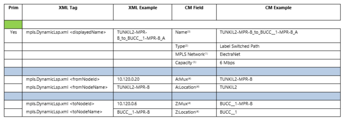
Field Mappings for LSP TCs
NOTES:
1)Comes from general configuration parameters the DSE. Refer Section 4.3.1
2)TC is always Label Switched Path
3)First name of matching duplex LSP pair is used for uniqueness. This assumes that the order of the matching pair from SAM do not change over time
4)LSP A and Z Location and Mux need to be resolved using NodeId
5)Since Label Switched Path doesn’t directly have a capacity. It will be taken from the highest capacity child LSP Path
Field Mappings for LSP Path TCs
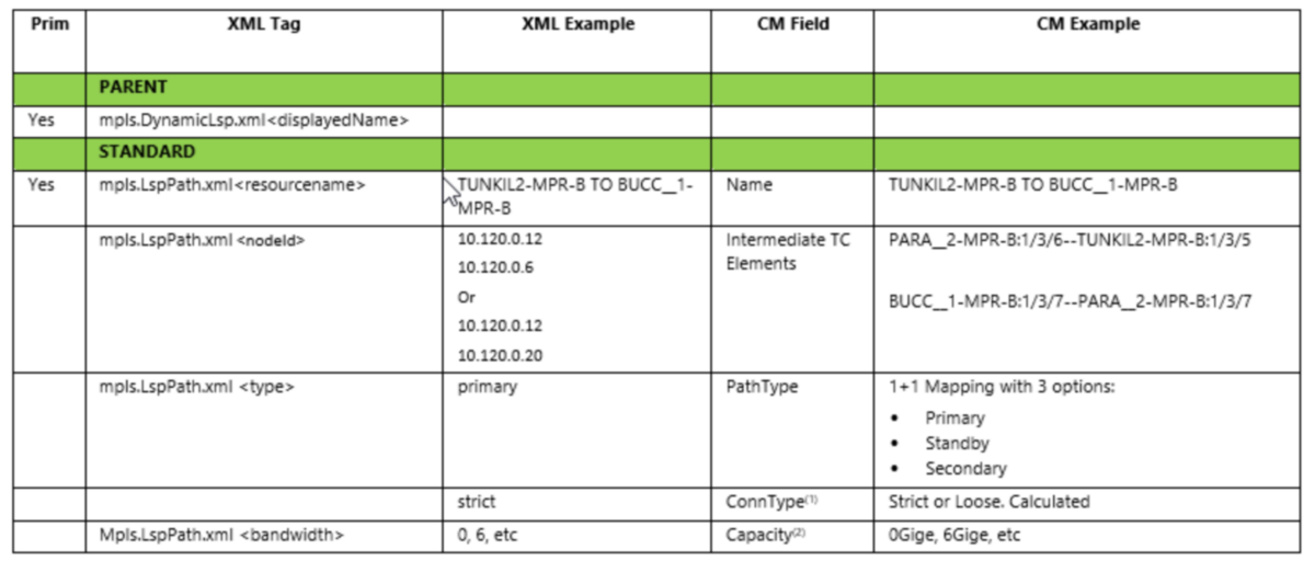
NOTES:
1)Calculated field. Strict if there Hops, Loose if no hops
2)Capacity mapping comes from rates mapping in general configuration
LSP Hierarchy