VPLS VPN
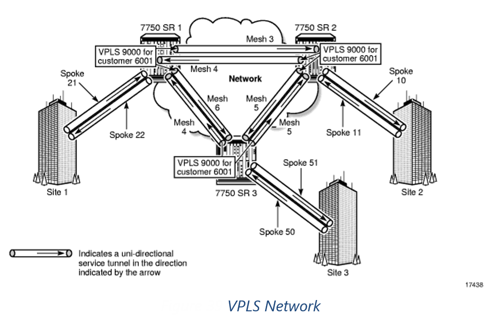
VPLS is presented with the same structure in Nokia/Alcatel SAM as VLL in that multiple VPLS with the same Service IS are represented under one VPLS container. The primary difference being that sites can have more than 2 interfaces and multiple sites can be joined with a mesh or spoke arrangement of service tunnels / Pseudowires.
Note that similar to VLL VPLS can exist within a single router/switch with no service tunnel / Pseudowire transport.
SAM Modelling
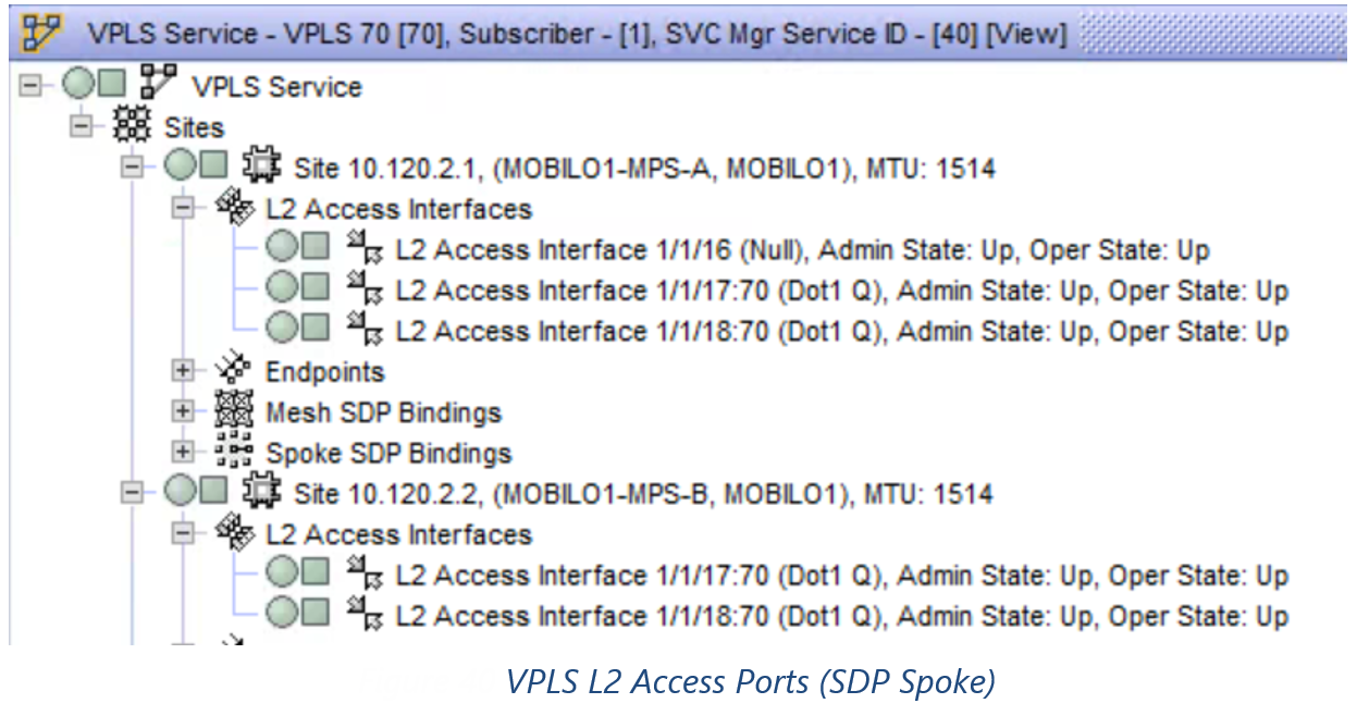
Nokia/Alcatel SAM Models VPLS with the following hierarchy:
VPLS -> SITES -> L2 Interfaces -> Service Tunnel
ConnectMaster Modelling
In CM the VPLS will be modelled as VPLS with the following characteristics:
1)Service Tunnel Bindings – Technically L2 Services use Psuedowires as transport layer, however Nokia/Alcatel SAM reports everything as Service Tunnels.
n x SAP Ports created under a VSI (Virtual Instance)
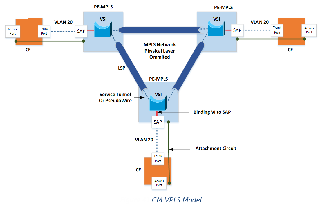
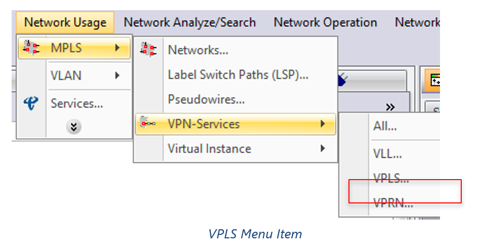

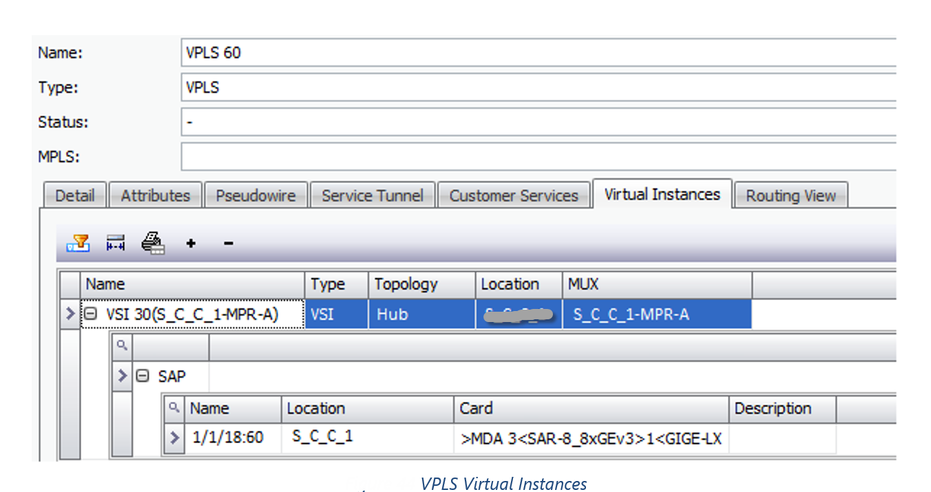
Note: From architecture point of view it is expected that there is only one inter-site VPN. The rule is as follows:
•Inter-Site -> Any Sites with SDP Binding
•Intra-Site -> Any Sites with no SDP Bindings
A new VPLS is created for each Intra-Site VPLS.
Field Mappings
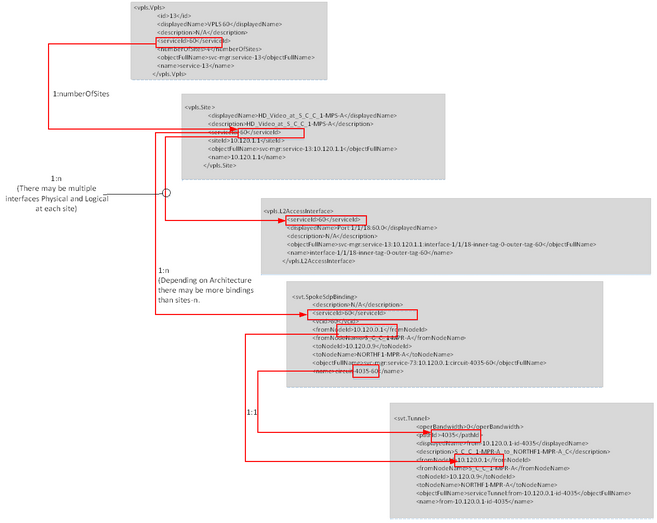
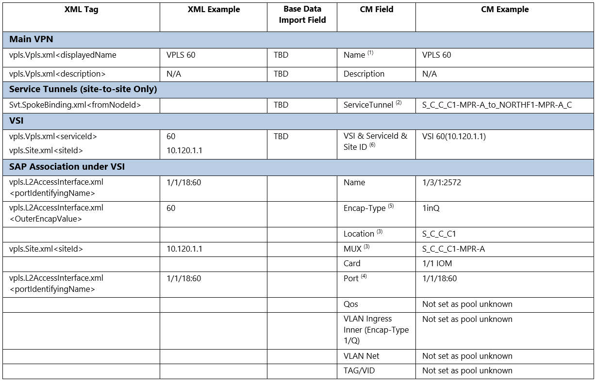
Source File – vpls.Vpls.xml (Initial Data Source for VPLS)
Source File – vpls.Site.xml (List of Sites associated with SAM VPLS Element)
Source File – vpls.L2AccessInterface (Provides associated SAP)
Source File – svt.SpokeSdpBinding.xml (Service Tunnel Binding Point to VPLS)
NOTES:
1)Since SAM-O doesn’t provide a unique name for each VPLS inside a SAM VPLS Element. A new name will be created using the description. Name = <displayedName> & (<description>)
2)Local VPLS don’t have any Service Tunnel
3)Need to resolve Mux from <siteId> IP Address
4)Need to resolve Card/Port from <portIdentifyingName>, Ports can be Physical or Virtual Sub-Ports
5)If <OuterEncapValue> = 0 then Encap-Type = Null, otherwise = 1inQ
6)VSI Name will be created as VSI & ServiceId & (Site ID)
XML VPLS Hierarchy
