Modelling Improvements

Building Blocks |
To support VPRN and better modelling VPLS the following building blocks are now available: 1)Creation of a MPLS Domain 2)Creation of LSPs over physical paths between each PE 3)Creation of Pseduowires over LSPs 4)Creation of Service Tunnels over LSPs – NEW! 5)Creation of VPN 6)Definition of VPN Type – Spoke, Mesh, etc – NEW! 7)Creation of VI (VRF or VSI) - NEW! 8)Association of Pseudowires to the VPN 9)Association of Service Tunnels to the VPN – NEW! 10)Association of SAPs to VI - NEW! 11)Association of IP Addresses to VI (VRF Only) - NEW! 12)Simplified Creation of CE Attachment Ethernet Circuits – NEW! 13)Support for Virtual Sub-Ports SAP – NEW!
|
Backwards Support |
Previous VLL and VPLS models can still be used and will be preserved during the upgrade. |
|
|
Virtual Instance |
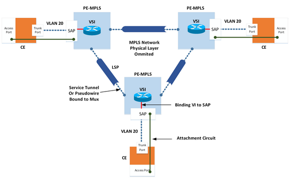
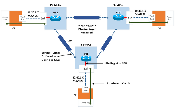
A major change to the previous model is the introduction of a VI object. The VI Object can either be VSI Virtual Switching Instance (VPLS) or VRF Virtual Routing Function (VPRN). SAPs are first assigned to a VRF or VSI. The VI are then assigned to the VPN.
|
Attachment Circuit |
Previously users would model VPLS customer services using Ethernet TC E-LAN. Multiport option would be used to represent each drop point in the VPLS. This representation was often confusing and meant that drop legs could not be protected. The new model aligns with RFC 4762 and allows user to create Attachment Circuits. These circuits only need to be routed from the end device up to the nearest SAP. This simplifies connectivity and allows protecting of the edge TC. |
|
|
VPRN Model |
|
|
|
VPLS Model |
|