Huawei DCP: 2-Channel Optical Path Protection Unit

Functional modules and signal flow of the DCP board (reference: Hardware Description, Issue 01, Date 2010-12-31, Huawei Technologies Co., Ltd. 2010)
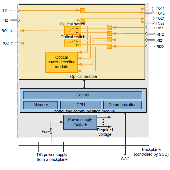
From the above diagram of the DCP card we can see that transmission signal received for one channel on TI1 interface splits the signal to output interfaces TO11 & TO12 as working and protection paths. The second channel on interface TI2 works the same way with TO21 & TO22 interfaces.
On the receiving direction, signal from RI11 & RI12 interfaces pass through an optical switch to RO1. Switch selects which signal to pass through based on the optical power. For the second channel RI21 & RI22 works the same way with the interface RO2.