Routing via a Link Aggregation TC

Description
This example shows a simple example of routing a TC across multiple hops, one of which is a Link Aggregation TC.
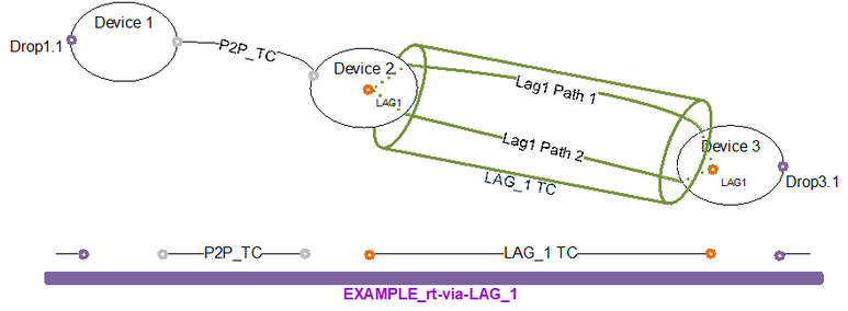
The end to end circuit will route via each of the objects shown.
Procedure
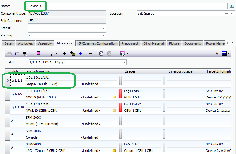
1.Create a Link Aggregation TC
a.Create a Link Aggregation TC as per the documentation.
Here the Link Aggregation TC has been created grouping two LAG paths between devices, all of which have been named as per the diagram.
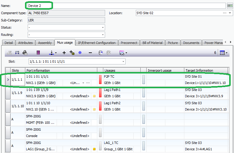
2.Configure Additional Links and devices
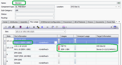
a.As many links of compatible types can be used as are needed. Here the TC named P2P TC has been created, as have the drop ports at each end.
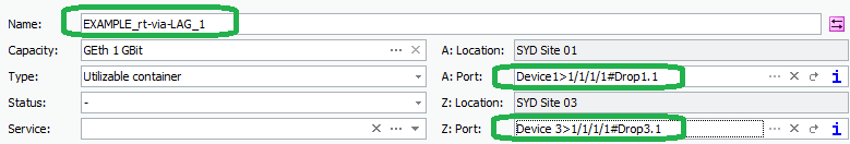
3.Create an end to end TC,
a.Create a new Ethernet TC
b.Assign the “drop” ports as the A and Z ports for the TC
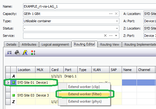
4.Route the TC via the P2P and LAG TC’s
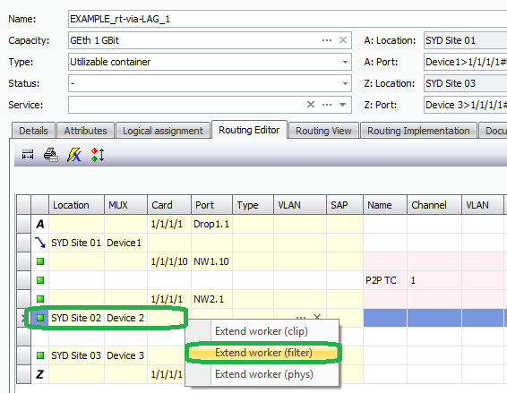
a.From the Routing Editor tab, extend the worker path via standard routing editor functionality. In this example, the TC is extended by filter.
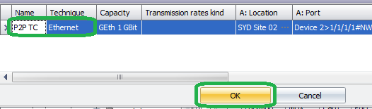
b.Here the P2P TC is selected as the first hop.
c.The worker is again extended. Here we again use the option to extend by filter, though any of the available extend options can be used.
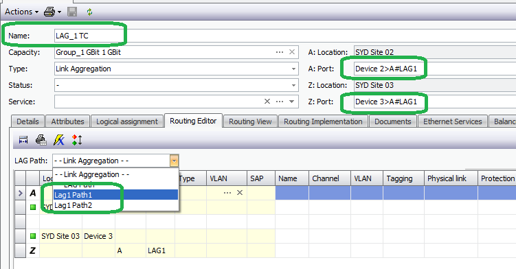
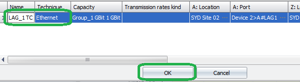
d.Here the filter finds the link aggregation TC called LAG_1 TC which is used to extend the end to end circuit.
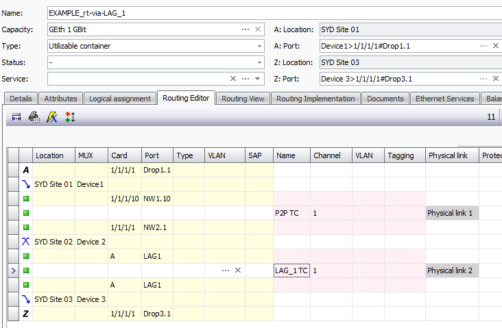
e.The resulting routing editor tab shows the P2P TC, LAG_1 TC and the VGP’s (“LAG1” at each end of the Link Aggregation TC).
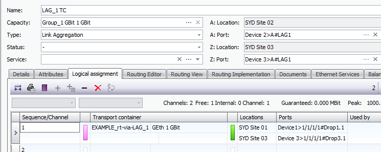
f.The end to end circuit is also visible in the Logical assignment tab of the link aggregation TC.