TC Detail – Routing View

Routing view |
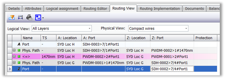
Switching to the tab “routing view”, you get an overview on the transport container, which the signal is contained in. Here you can take a detailed look to all physical paths along the transport container connecting the multiplexers.
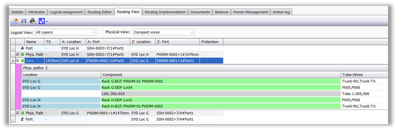
Physical paths which are directly used by the transport container without transmission layer between are highlighted grey. Physical Paths which are not directly used by the transport container using transmission layers between are highlighted pink.
For each physical path the fibre/wire details can be expanded.
|
||
Options |
Two filters help the user to get a better view both at logical and physical view:
|
||
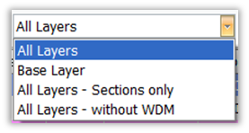
Logical View |
With this filter the user can adjust the view depending on the layer he/she want to be displayed:
•All Layers (6.75: ‘Normal’):Show all Physical Paths independent of which layer above the TC is assigned •Base Layer (6.75: ‘Routing Table’): Show Physical Paths where the TC is assigned to as a direct parent •All Layers–Sections only (6.75: ‘Without Mux int.’): Like ‘All Layers’, but show only aggregate-sections (hide sections between tributary ports at the Mux) •All Layers–without WDM (6.75: ‘Without WDM’): Like ‘All Layers’, but hide WDM links
|
||
Physical View |
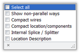
The user can organize the physical view checking the corresponding box:
•Show non parallel ways: The tabular view shows also non parallel paths (extra rows are displayed containing the no common points of the paths) •Compact wires: Wires with the same path are grouped in the same view •Compact location/components: Add more details •Internal Splice /Splitter: Shows the connecting points. •Location Description: Hide/show the column “Location description”
|
||
Report |
A report of the Routing-View is available: |
||
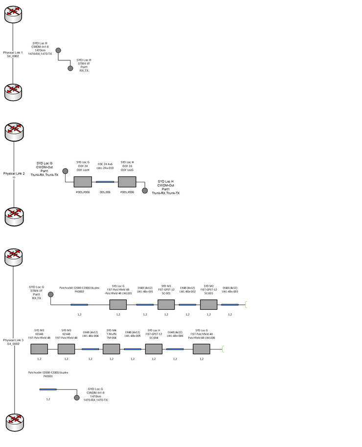
Diagram |
The following standard diagram in Visio can be selected:
|
||
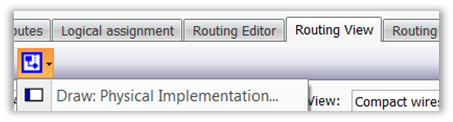
Physical Implementation |
Selecting Draw: Physical Implementation a visio-schema is generated automatically showing all physical paths related to the corresponding transport container.
|
|
|
|
|