Auto-routing wizard

The below describes the features and usage of the auto-routing wizard for the user.
Launch |
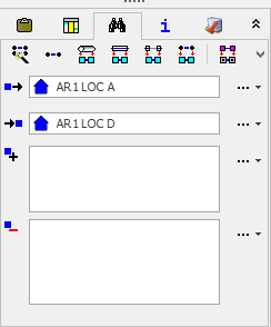
The Auto-routing tool can be launched from: -The quick-access search area: select start and end locations to launch the search: -Note: the fields in the quick access area can be populated by drag and drop from the explorer tree.
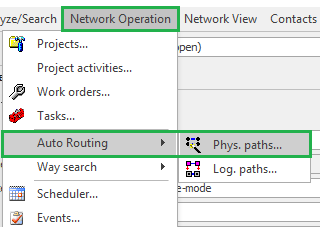
-It can also be opened from the menu, under Network Operation, Auto Routing, Phys paths…
|
Navigation |
The user can step between steps in the wizard by clicking to select the step name in the indication bar, or the Back and Next buttons to the left and right respectively of the indication bar
|
1. Start |
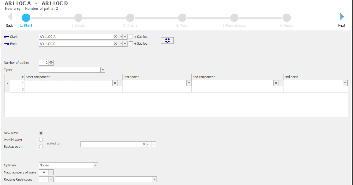
Start screen in the auto-routing:
User can define: -Start and end locations (including via drag and drop from explorer) -Swap the selected start and end locations
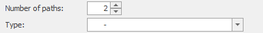
-Number of paths. The number of paths required end to end as a result of the search and resulting work-order. -Type of path. Can be undefined, “Master” path or “Backup” path.
-Start and end components and connection points. Components can be selected by drag and drop. Points are selected from a drop-down selection.
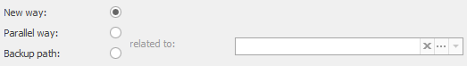
-Way type: New way is searching for a new circuit route without any constraints or reference to another route. -Way Type: Parallel way allows selection of an existing path(s) that the new path should follow (using the same cables between locations on the route). -Way Type: Backup Path allows selection of an existing Master path to which the new path should be diverse. -
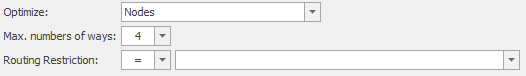
-Optimize option, can be by the number of nodes in the path, length, or the calculated optical loss. -Max number of ways: this gives the number of cable way results to propose. -Routing restriction: where used, routing status can be used as a master filter option to include or exclude sites and cables from the found cable ways. -
|
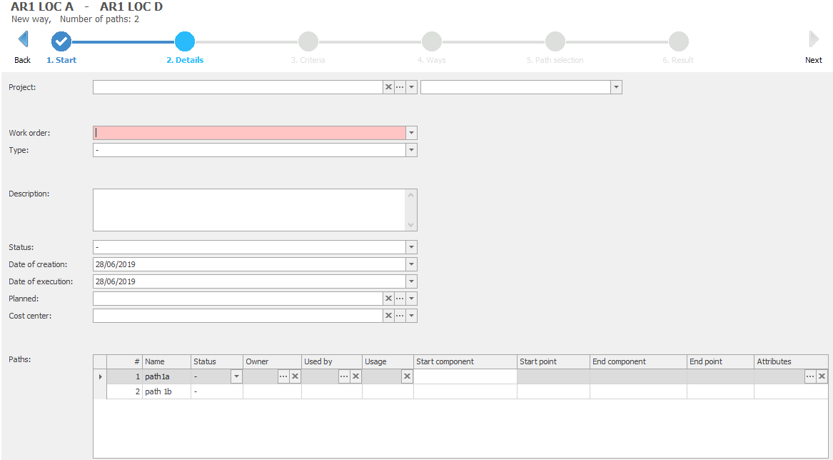
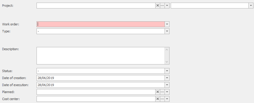
2. Details |
Details screen in the auto-routing:
User can define: -Project and activity -Work order name (Mandatory field) -Type of work order. Work order types can be configured in the library. -Description -Work order status. -Creation and execution dates -Planned. Assign an organization (person /department / company) to identify the entity responsible for the planning. -Cost center. Record an organization (person /department / company) to identify the entity responsible for the costs associated with the work.
-Paths: Record path name(s), status, owner and user, usage, attributes of the path(s) to be assigned on execution / creation of the end-to-end path.
|
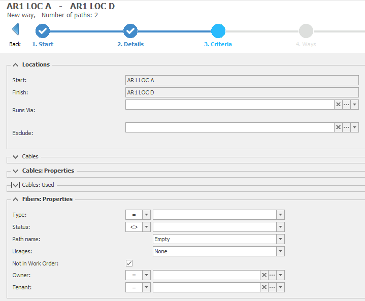
3. Criteria |
Criteria screen in the auto-routing:
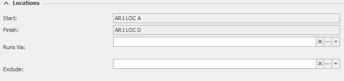
User can define: -Edit the Location start and end, and criteria to run via or exclude selected locations
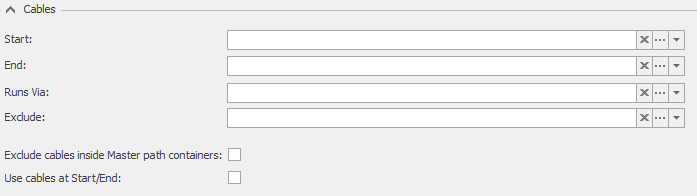
-Edit the selected cables for inclusion or exclusion in the in the found cable way
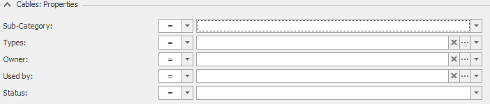
-Edit the cable properties, e.g. types, sub-categories, ownership, usage and status to be included or excluded from the found cable way
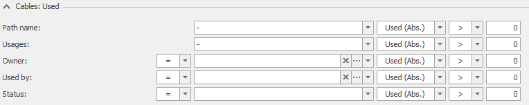
-Edit the cable usage properties for inclusion or exclusion from the found cable way based on the utilization of the fibers within the cables, with criteria that can be defined with either percentage values or absolute values for filtering.
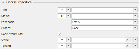
-Edit the properties of the fibers that can be treated as available in the path selection step. The below image shows the minimum recommended settings for most use cases.
|
4. Ways |
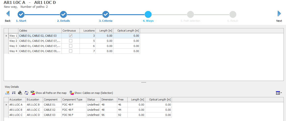
Ways screen in the auto-routing:
User can: -Review the proposed cable ways. In the list of ways, select a way to show the locations, cables and usage information of the selected way in the lower part of the window.
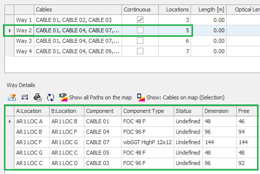
-User can show and compare the paths on the map, with the ability to select and highlight each resulting way separately for ease of comparison, or to select a sequence of cables from a selected way to highlight them individually on the map.
-Select the desired cable way before stepping into the path selection screen allows to find the path within the selected way.
|
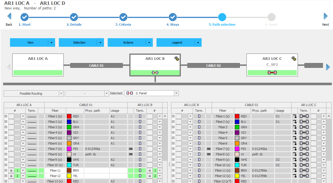
5. Path Selection |
The Path Selection screen:
The view shows only the incoming and outgoing cables from each node that are relevant to the selected cable path.
Menu bar:
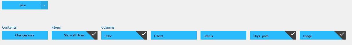
-View sub-menu:
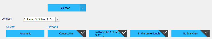
oContents: Changes only. This option is unchecked by default. It reduces the shown symbols in the node navigation to show only nodes where changes are required to make the path oFibers: show all fibers. When checked this shows all fibers in the displayed cables, otherwise only available fibers are displayed in the fibre selection panes. oColumns: this lists the fibre attributes to be displayed in the fibre selection panes. By default, the fields selected are inherited from the library, but can be modified for the active wizard by the user if needed. -Selection sub-menu:
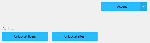
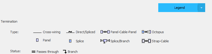
oConnect. Choose within the current workflow if all the allowed connection types should be possible within the current auto-routing session and remove unwanted connection models. oSelect: Automatic. This refreshes the automatic selection after changes to the selection options. oOptions: Consecutive, In blocks, In the same bundle, No branches. These options are as per the library settings. They can be adjusted for the current auto-routing session. -Actions sub-menu: - oActions: Unlock all fibers and unlock all sites. After manual update of the automatic selection, the system applies a lock to keep the manual selection automatically. These actions provide a quick way to remove those locks across all sites where manual changes may have been made. -Legend: - oTermination type. This legend of symbols used to show the terminiation type of fibers in the selected site within the fibre selection pane. The symbols indicate the termination type / connectivity model identified by auto-routing, if any. oStatus. This legend shows the state of existing connections. The symbols indicate if the fibers have existing through connections following the desired cable way, or if they are connected but branching in another direction. No symbol is shown if there is a connection needed, of there are no connections.
Node navigation:
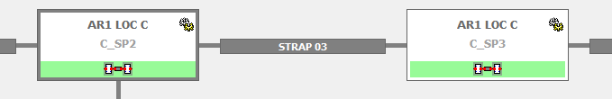
-This navigation bar shows the connectivity nodes and cables between them that are proposed for the autorouting. -Nodes with changes required are indicated with a symbol as shown:
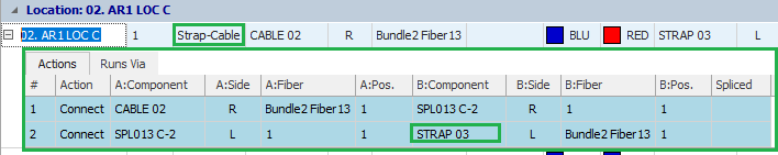
-Generally, the nodes represent the locations on the path, however in locations where a strap cable is identified and required, the nodes represent the connected containers of the incoming and outgoing cables. If a relevant strap cable is found, it is shown in the display. If the strap cable is not found, a “missing cable” message is given to the user to add or updated the data to allow the user to continue to the next step in the auto-routing.
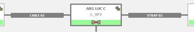
-The selected node for displaying fibre details in the fibre selection panes is highlighted in gray as shown/
-The navigation bar includes buttons to shift the view of the nodes left and right within the screen to make off-screen nodes and cables visible.
Possible Routing: -Where multiple connection types are possible for the fibers displayed, those options are displayed to the user in a drop-down menu. The selected connection technique is shown
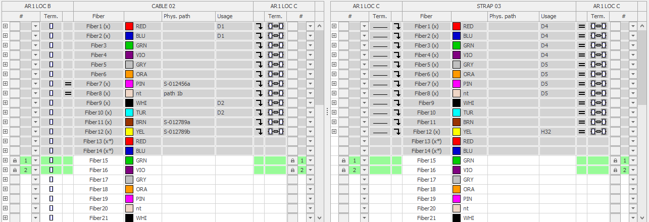
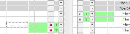
Fibre selection panes: - -The user can review the found selected fibers at each node, with visibility of oFibers available are shown with a white background. Fibers not selectable for auto-routing are greyed-out. oConnectivity models in use on the fibers. oConnection status if fibers are connected through the site in the right direction, or branching in another direction, or not connected through. oFibre numbering and selected fibre details. oManual selection of fibers automatically sets a lock so that the user can then run the automatic selection function from the menu without losing the manually selected fibers. o
|
6.Result |
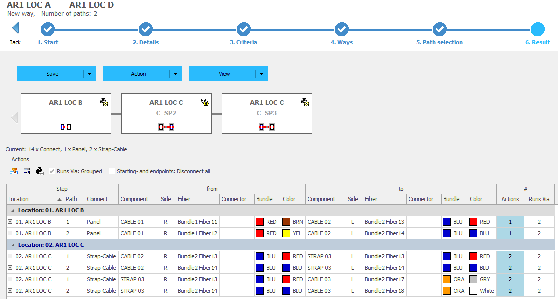
The Result screen:
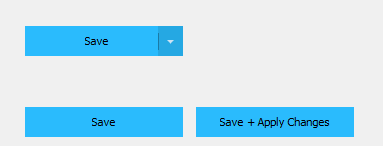
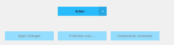
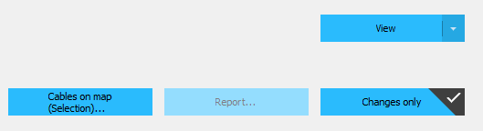
Menu bar: -Save sub-menu: - oSave. Saves the changes identified in the result as a work order. This is a list of changes that can be executed at a later date. oSave and Apply Changes. This saves the work order AND executes or applies the changes automatically in one click. -Action sub-menu: - oApply changes. If the work order is saved but not yet executed, it can be run while still within this window using this action. After closing this window, the workorder can still be executed within the work order details. oProtection way. This allows for creation of a new work order to generate a protection path to the current path. oComponents: Automatic. Automatic creation of some element types. Deprecated function for current release, but may be reintroduced in the future. -View sub-menu: - oCables on map. Highlights the resulting path on the map. oReport. If the work order is saved, a report can be run from the defined reports. oChanges only. Only show nodes where changes are required. Selected by default.
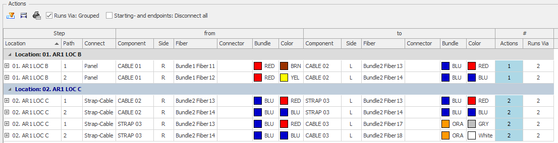
Changes pane: Grouped list of changes per Location. Gives a list of changes needed to make the continuous path(s).
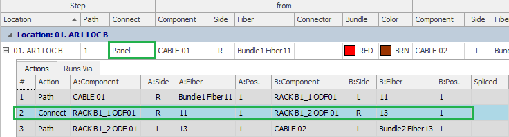
-For each location and for each path, the details of the incoming and outgoing cables and fibers are visible, with bundle and fibre colours plus the number of actions needed. -Expanding each row gives the detail of existing and new connections that form the continuity within the nodes where changes take place. If relevant, disconnect actions are also displayed.
-These details are also visible for display and reporting directly from the work order detail.
|