Setup
A minimum level of configuration is needed prior to using the auto-routing wizard in a reliable way. In addition certain customers with specific connectivity models to be supported may have some activities to ensure or update data to allow it to be identifiable based on the described requirements of the selected models.
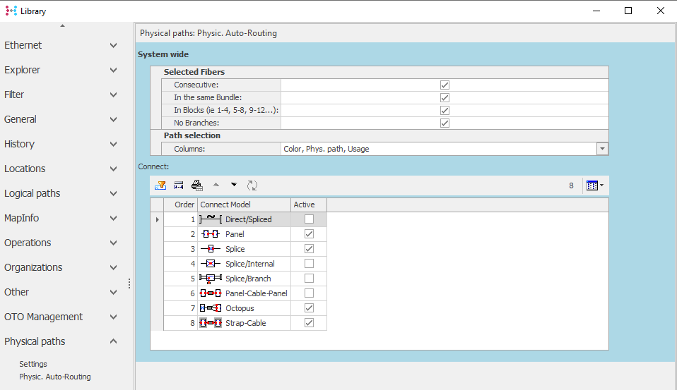
Under Library Settingsà Physical Paths: à Physic Auto-routing
Library Settingsà Physical Paths: à Physic Auto-routing
|
Settings:
|
|
NB: All Settings are System-wide.
|
Description of the settings and their function:
Section |
Item |
Description |
Selected Fibers |
Consecutive |
If field is checked (default): if more than 1 fibre are required in the path, then they are selected on consecutive fibres / points in the path search. If unchecked: selection can automatically take non-consecutive fibres in the path search. |
Selected Fibers |
In the same bundle |
If field is checked (default), the system will only propose fibres in the same bundle/tube within each cable. If unchecked: selection can automatically select fibres across multiple bundles/tubes in the path search. |
Selected Fibers |
In blocks |
If field is checked (default), the system will only propose fibres in the blocks corresponding with the selected number of fibres. For example, if 6 paths are required via a 24-fiber cable, then the system will only propose (if available) fibre ranges: 1-6; 7-12; 13-18; or 19-24. If unchecked: System can select the first available fibres based on remaining selection options.
|
Selected Fibers |
No Branches |
If field is checked (default), the system will only propose fibres whose existing terminations are not already connected to a path heading in another direction to the desired way. If unchecked: System can propose to split existing connections and reconnect fibres in the desired direction.
|
Path Selection |
Columns |
Drop-down selection list of fields that may be displayed to the user by default within the path selection window.
Fields: -Color: fibre colour -F-Text: f-text value of the displayed fibre -Status: status of the displayed fibre -Phys. Path: physical path name using displayed fibre -Usage: Fibre usage (signal or transport container)
|
Connect |
Connect options |
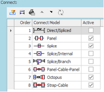
Connect Models should be disactivated based on your used connectivity modelling. If unsure, contact your support team to discuss the appropriate model selection.
The connect options can be re-ordered to change the order of preference for the proposed connection type by default. This order applies where multiple connection options could apply in a given location within the path selection step. The system will attempt to propose the preferred option based on the ordering defined here.
|
Connect Options |
Direct Spliced |
The Direct Spliced model is only appropriate for customers who choose to directly connect fibers together, without connecting via an intermediate Splice (T-Socket, Cassette) object. The system therefore can use or propose to connect fibers directly without generating intermediate connections.
|
Connect Options |
Panel |
This model is generally expected to be in use for all customers. It allows for finding paths that terminate on ODF / Panel ports and supports automatic connections between the found ports.
|
Connect Options |
Splice |
This splice model is used for customers documenting their splices with a Container, having one or more Splice objects (T-Socket, cassette). Fibers are connected left and right of the cassette to document the continuity and the position of the splice within the splice object and its container.
|
Connect Options |
Splice Internal |
Variant on the Splice model, in which the internal connections of the T-Socket are manipulated to create and manage connectivity.
|
Connect Options |
Splice / Branch |
Another splicing model where 2 connections points on each side of the T-Socket are used. Incoming cables are connected to outer connection points, and the inter-fibre connectivity can be managed by creating connections between the inner points.
|
Connect Options |
Panel-Cable-Panel |
Connection option between panels, where the system can look for “connectorized” cables to create patches between panels. These are generally in use only in some customer environments.
|
Connect Options |
Octopus |
This supports Octopus cables, where one end is connected via splicing to another cable, and the other has connectors documented, indicating its fibers can be connected to ports on a Panel / ODF.
|
|
Pre-requisite for Octopus cable |
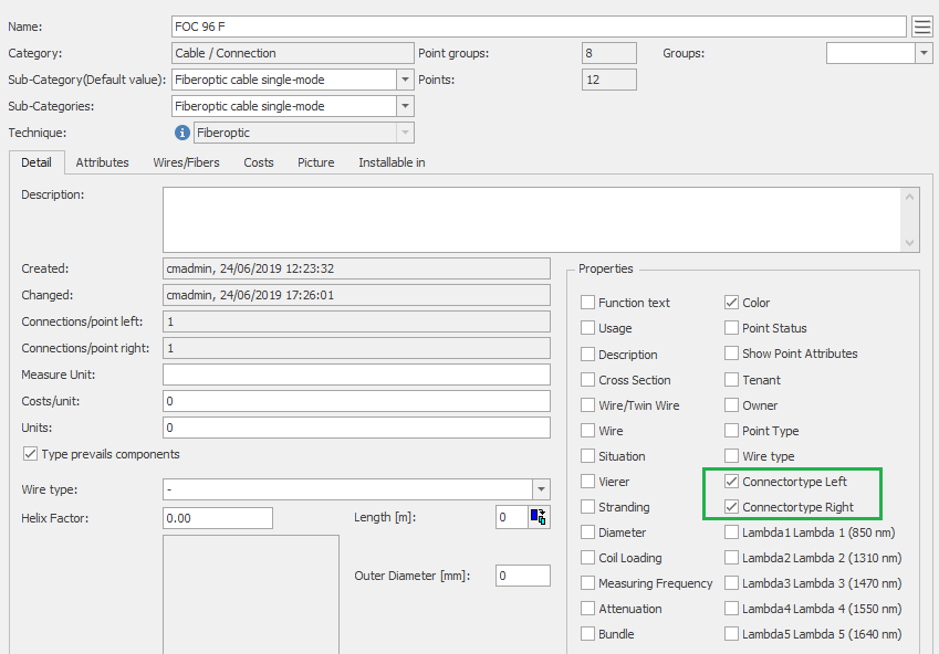
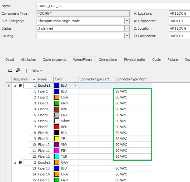
To be identified, the Octopus cable must: -Have one end with documented Connectors: In the component type for cables to be used as octopus cables, add the optional fields to enable connector types.
-If the type is only to be used for octopus cables, then the connector type can be documented on fibers in the cable type. -If the type is used only in some cases for octopus cables, then user must update the octopus cable details to document the type at the relevant side of the cable, for example
-End containers should be documented for any “internal” cables such as this that should be considered for auto-routing.
|
Connect Options |
Strap Cable |
A strap cable is an “internal” cable within a location that connects splice enclosures. In this case, where incoming and outgoing cables terminate in different enclosures, a Strap Cable is needed. The connections at each end of the strap cable are identified and when changes are needed these new connections are included in the resulting work order.
When Strap Cables are required, it must exist in the location. The system will NOT propose to create the strap cable automatically.
|
Pre-requisite for Strap Cable |
To be identified as a strap cable, the cable should: -Have the end containers documented (as per any “internal” cables such as this that should be considered for auto-routing).
|
NOTES:
-It is important to verify that only the connect options in use in the target environment are active in the above settings.


