Multiplexer shapes

|
To create a user-defined multiplexer shape with which the function “Automatic populate” can be used, proceed as follows: |
|
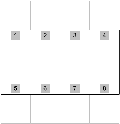
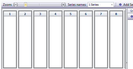
1.Draw mux layout
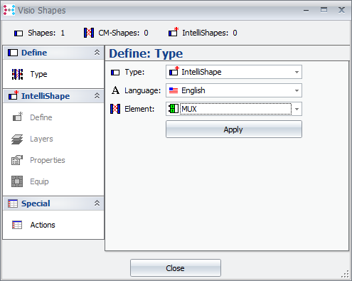
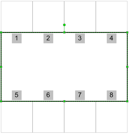
2.Group individual shapes 3.Define the grouped shape as multiplexer (CM type)
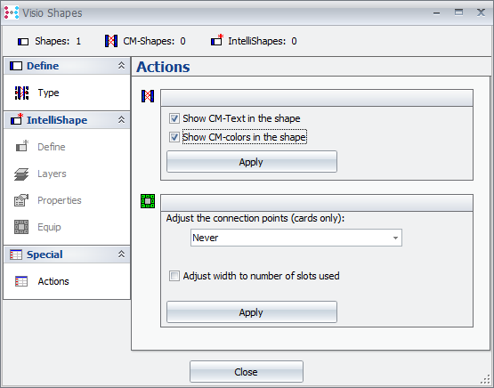
4.Define sub shape for CM text and/or CM colour: |
|
Select sub shape
CM -> Define -> Define shape -> Special/Actions
|
|
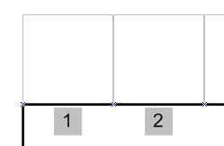
1.Insert connection points in the positions in which the cards of the respective slot are to be placed.
The connection points can be placed within the master shape by pressing the <CTRL> key. |
|
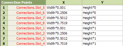
1.Open the shape sheet (only possible in Visio.exe) and name the connection points with the respective slot names as it is called in ConnectMaster, e.g. „Slot_1, Slot_2…“ (‚Connections' is automatically given by the system) To make sure that the connection points are automatically positioned into a grid, activate the according grid options before you start positioning under Extras / Align and Agglutinate. |
 =>
=> 
|
The name of the connection points must match the slot name of the corresponding multiplexer type with prefixed “Slot_”. |
After entering these characteristics, the shape sheet can be closed. |
|
1.Draw the mux shape to the user-defined stencil (MeineShapes.vss) 2.Call the shape the same as the multiplexer type in CM was called: SDH_MUX |