Interconnection of WT trail

Routing table |
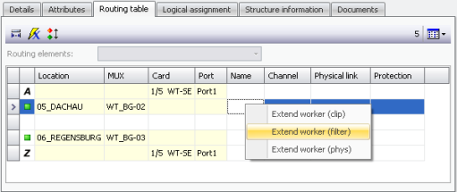
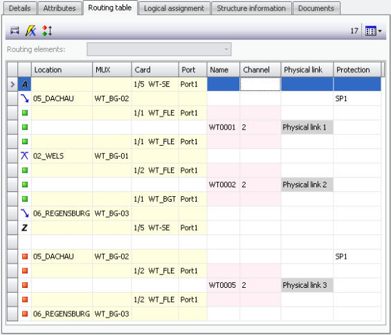
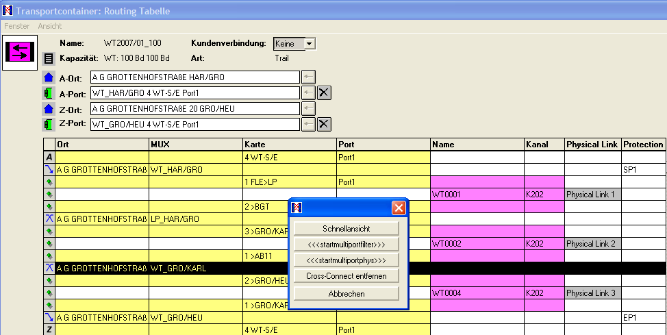
Call of the routing table of the WT trail
and interconnection in WT0001:
|
|
Based on the channel and/or frequency range definition on the card port, the trail is automatically interconnected in this range.
|
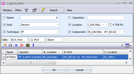
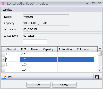
Manual selection of frequency range |
If no channel and/or frequency range were defined on the port, this range is selected manually when interconnecting in the 1st WT section, because a WT trail always lies in the same frequency range within all WT sections.
|
|
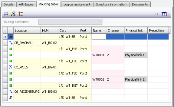
“Extension” of interconnection up to end device:
|
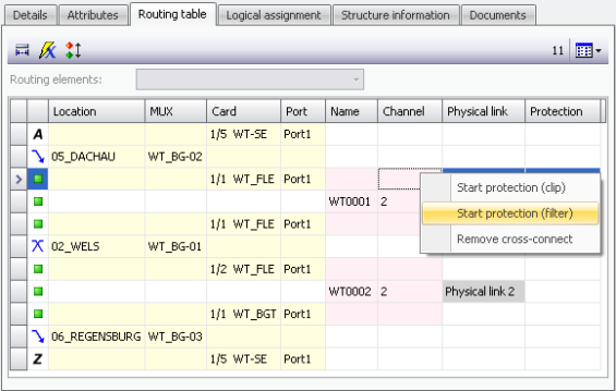
Protection |
The protection interconnection is called from the WT device by calling the context menu and selecting the action “Start protection”:
|
|
If the protection path continues uninterrupted up to the end point, the end mark can be automatically set via the button
|
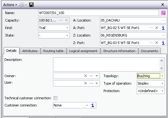
Multiports |
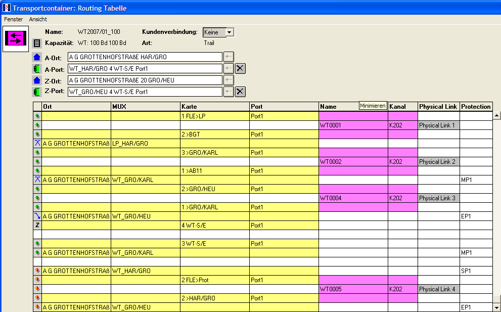
If the trail needs to be available on several ports (multiports), the topology type must be switched to “Bus ring2 in the TC detail.
|
Multiport allocation |
In the routing table, a multiport can be allocated via the context menu:
|
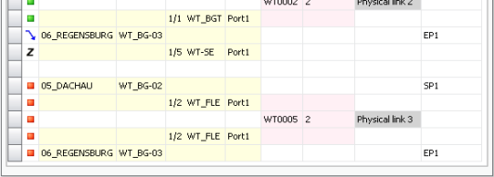
Representation of multiports in routing table |
|