Divide

|
In the task window “Divide”, various actions can be performed according to the selected line object in the map. |
|||||||||||||||
|
|
|||||||||||||||
|
In this task window, the individual partial actions are executed step-by-step. |
|||||||||||||||
|
||||||||||||||||
Divide |
A line object is “divided” in the following steps. |
|||||||||||||||
|
1.The level of the line object must be the current insert level (select “Level: Edit” in the context menu of the line object). 2.Select action “ 3.If the original line to be divided does not need keeping, select “Delete original”. 4.The end points A and Z are displayed at the line object. 5.If the mouse pointer is positioned at the line object, the distances from one end point to the position of the mouse pointer “A-X” and from the position of the mouse pointer to the second end point “X-Z” are displayed in green in the task window. |
|||||||||||||||
|
|
|||||||||||||||
|
1.By clicking on “Esc” or “Cancel”, the divide process can be cancelled at any time. 2.The line object is divided by clicking on the required division point. 3.The Info window is activated. The two newly created lines appear in the Info window. These two line objects are located on the same insert level as the original line. |
|||||||||||||||
For allocated line objects |
1.If the divided line was allocated to a ConnectMaster element, the two newly created line objects possess the same CmExKey as the original line object. |
|||||||||||||||
|
||||||||||||||||
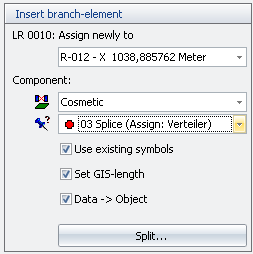
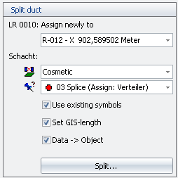
Insert & divide branch element: Empty pipe, insert: Shaft |
In both actions, an empty pipe is divided. A section then corresponds to the original empty pipe with changed Z location and Z component; a component (shaft) is inserted at the divide position and the 2nd section corresponds to a new empty pipe. |
|||||||||||||||
|
Hence these actions “Insert branch element” and “Divide: Empty pipe, insert: Shaft“ are combinations of MapXtreme and ConnectMaster actions: •MapXtreme: Divide line object and insert symbol object into the map at the divide position. •ConnectMaster: Automatic patch action “Insert branch element” and/or “Divide empty pipe“. |
|||||||||||||||
|
The step-by-step course of these two actions is described in the following: |
|||||||||||||||
|
1.Divide line object: see previous section “Divide”, Paragraph 1 to 7. 2.After clicking on the divide point, the sections “Insert branch element” and/or “Divide empty pipe” are displayed. |
|||||||||||||||
|
|
|||||||||||||||
|
Alternatively: |
|||||||||||||||
|
|
|||||||||||||||
|
In the following, the second part of the process is only described for “Insert branch element” because on the MapXtreme side, exactly the same steps are performed for “Divide: Empty pipe, Insert: Shaft“: 1.The empty pipe allocated to the divided line object must be reallocated to one of the two sub-lines “A-X” or “X-Z”. 2.For the component inserted at the division point, it must defined: •On which level the component must be placed after executing the ConnectMaster action. •Which symbol is to be inserted into the map? •Whether an automatic data exchange must be performed at the end (Data -> Object). |
|||||||||||||||
|
1.By clicking on “Divide”, the relevant ConnectMaster action is started and the new empty pipe is created in ConnectMaster. 2.The symbol object is inserted into the map at the division point and the two empty pipes and the inserted components are allocated to the two line and symbol objects as defined in Items 3 and 4. 3.The Info window is activated and the 3 objects are displayed. |
|||||||||||||||
|
|
|||||||||||||||
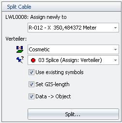
Divide: Cable, Insert: T-splice |
In this action, a cable is divided. A section then corresponds to the original cable with changed Z location and Z component; a T-splice is inserted at the divide position and the 2nd section corresponds to a new cable. |
|||||||||||||||
|
Hence “Divide: Cable, Insert: T-Splice” are combinations of MapXtreme and ConnectMaster actions: •MapXtreme: Divide line object and insert symbol object into the map at the divide position. •ConnectMaster: Automatic patch action “Divide cable”. |
|||||||||||||||
|
The step-by-step course of this action is described in the following: |
|||||||||||||||
|
1.Divide line object: see previous section “Divide”, Items 1 to 7. 2.After clicking on the division point the section “Divide cable” is displayed. |
|||||||||||||||
|
|
|||||||||||||||
|
1.The cable allocated to the divided line object must be reallocated to one of the two sub-lines “A-X” or “X-Z”. 2.For the T-splice inserted at the division point, it must defined: •On which level the T-splice must be placed after executing the ConnectMaster action. •Which symbol is to be inserted into the map? •Whether an automatic data exchange must be performed at the end (Data -> Object). |
|||||||||||||||
|
1.By clicking on “Divide”, the relevant ConnectMaster action is started, and the T-splice and the new cable are created in ConnectMaster. 2.The symbol object is inserted into the map at the division point and the two cables and the inserted T-splice are allocated to the two line and symbol objects as defined in Items 3 and 4. 3.The Info window is activated and the 3 objects are displayed. |
|||||||||||||||