Card/Module

Components of the category Card/Module have a special status.
They have both connection points and the option to be equipped. The connection points are grouped into 0 to n ports. The number of card slots for further cards/modules is also between 0 and n.
Characteristic |
Description |
|||||||||||||||||||||||||||||||||
|---|---|---|---|---|---|---|---|---|---|---|---|---|---|---|---|---|---|---|---|---|---|---|---|---|---|---|---|---|---|---|---|---|---|---|
Card in card |
Only one element of the same category can be integrated into a component of the category “Card/Module”. This is possible up to 3 levels: Network element – Card/Module – Card/Module – Card/Module |
|||||||||||||||||||||||||||||||||
Mode of operation |
The mode of operation must further be defined on the component type of the category “Card/Module“. The user can select between STM, WDM, WT, TF/TFH, IP/Ethernet or Mixed. The mode of operation defines which capacities and transfer rates can be defined on the card ports. |
|||||||||||||||||||||||||||||||||
Automatic generation of transport containers |
If this option is activated, a transport container is created by the system as soon as 2 ports are connected to each other via a physical path. |
|||||||||||||||||||||||||||||||||
Default value |
This value harmonises with the option “Automatic generation of the transport containers”. It supplies the components of the automatically generated transport container names. |
|||||||||||||||||||||||||||||||||
Attenuation/Resistance |
These characteristics can be changed at any time and can be subsequently inherited to the component type level. |
|||||||||||||||||||||||||||||||||
Capacity and capacity allocation |
A capacity is additionally allocated to a component type of the category “Card”, which is managed in the capacity allocation. This function defines how the total capacity of the card on the ports is allocated. Depending on the mode of operation, the transfer rate is defined as capacity, number of channels, or frequency. Standard transfer rates are predefined. If further transfer rates need to be documented, they are to be added to the library. |
|||||||||||||||||||||||||||||||||
Card ports |
Card ports are generated automatically according to the specifications of the capacity definition and allocation and have the following characteristics:
|
|||||||||||||||||||||||||||||||||
Mode of operation/Mixed ports |
The mode of operation of the card port is defined by the mode of operation of the card. For cards with mixed operation, the ports of a card can be allocated different operations – mixed ports. |
|||||||||||||||||||||||||||||||||
Usage control |
In the column “Check”,“Behaviour” can be defined when using a card port with a transport container. The following available options can be selected:
|
|||||||||||||||||||||||||||||||||
|
Accurate capacity check The transfer rate of the transport container ending on the port must be identical with the transfer rate of the port. |
|||||||||||||||||||||||||||||||||
inner/outer ports |
Maximum capacity check The capacity of the transport container ending on the port must be equal or smaller than the capacity of the port. |
|||||||||||||||||||||||||||||||||
Example 1: PDH – SDH |
No usage check The capacity of the transport container ending on the port is not checked. |
|||||||||||||||||||||||||||||||||
|
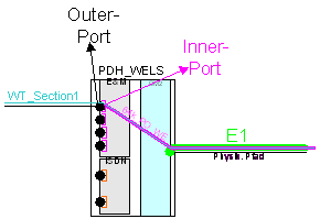
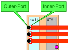
Use inner ports (inner/outer port) When defining a port as inner/outer port, two transport containers can be placed on the port. The port is thus used as an interface. See below examples for details |
|||||||||||||||||||||||||||||||||
|
Outer port corresponds to the physical connection side. Inner port corresponds to the internal logical port. |
|||||||||||||||||||||||||||||||||
|
|
|||||||||||||||||||||||||||||||||
|
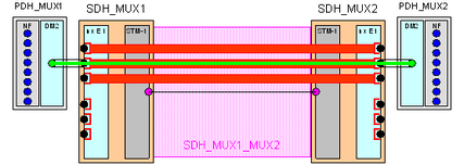
If the outer port is used with a TC, the latter is directly wired-up in the TC ending on the inner port. The following dependencies must be observed when using the port with transport containers:
|
|||||||||||||||||||||||||||||||||
|
A peculiarity as regards port usage is port usage with a customer connection because in this case, there is no port usage check, i.e. port usage can always be higher than port capacity. |
|
|
|||||||||||||||||||||||||||||||||
Card in card |
Only one element of the same category can be integrated into a component of the category “Card/Module”. This is possible up to 3 levels: Network element – Card/Module – Card/Module – Card/Module
|
|||||||||||||||||||||||||||||||||
Mode of operation |
The mode of operation must further be defined on the component type of the category “Card/Module“. The user can select between STM, WDM, WT, TF/TFH, IP/Ethernet or Mixed. The mode of operation defines which capacities and transfer rates can be defined on the card ports.
|
|||||||||||||||||||||||||||||||||
Automatic generation of transport containers |
If this option is activated, a transport container is created by the system as soon as 2 ports are connected to each other via a physical path. |
|||||||||||||||||||||||||||||||||
Default value |
This value harmonises with the option “Automatic generation of the transport containers”. It supplies the components of the automatically generated transport container names.
|
|||||||||||||||||||||||||||||||||
Attenuation/Resistance |
These characteristics can be changed at any time and can be subsequently inherited to the component type level.
|
|||||||||||||||||||||||||||||||||
Capacity and capacity allocation |
A capacity is additionally allocated to a component type of the category “Card”, which is managed in the capacity allocation. This function defines how the total capacity of the card on the ports is allocated. Depending on the mode of operation, the transfer rate is defined as capacity, number of channels, or frequency. Standard transfer rates are predefined. If further transfer rates need to be documented, they are to be added to the library.
|
|||||||||||||||||||||||||||||||||
Card ports |
Card ports are generated automatically according to the specifications of the capacity definition and allocation and have the following characteristics:
|
|||||||||||||||||||||||||||||||||
|
|
|||||||||||||||||||||||||||||||||
Mode of operation/Mixed ports |
The mode of operation of the card port is defined by the mode of operation of the card. For cards with mixed operation, the ports of a card can be allocated different operations – mixed ports.
|
|||||||||||||||||||||||||||||||||
Usage control |
||||||||||||||||||||||||||||||||||
|
|
|||||||||||||||||||||||||||||||||
inner/outer ports |
Examples of the use of inner ports for the realisation of a port as an interface are shown in the following.
|
|||||||||||||||||||||||||||||||||
Example 1: PDH – SDH |
Example 1: Transition from PDH via SDH •Inner port: SDH - VC-12 Container (is routed via STM-1) •Outer port: PDH - E1-TC, is automatically routed via VC-12 |
|||||||||||||||||||||||||||||||||
|
|
|||||||||||||||||||||||||||||||||
|
Outer port corresponds to the physical connection side. Inner port corresponds to the internal logical port. |
|||||||||||||||||||||||||||||||||
|
|
|||||||||||||||||||||||||||||||||
|
If the outer port is used with a TC, the latter is directly wired-up in the TC ending on the inner port. The following dependencies must be observed when using the port with transport containers:
|
|||||||||||||||||||||||||||||||||
|
A peculiarity as regards port usage is port usage with a customer connection because in this case, there is no port usage check, i.e. port usage can always be higher than port capacity. |
Example 2: PDH – SDH |
Example 1: Transition from WT via SDH •Inner port: PDH – 64 Kbit Container (is routed via PDH- E1) •Outer port: WT – 3.4 kHz Section TC, is automatically routed via 64 Kbit
|
|||||||||||||||||||||
|
||||||||||||||||||||||
Application |
When using an inner/outer port with a transport container whose capacity is equivalent to the port capacity, the system asks which port is to be allocated (inner or outer port).
|
|||||||||||||||||||||
Capacity preconnection |
The capacities defined on the ports can be preconnected. This means that the content of a port can be directly wired up into another port according to definition. For more detailed applications, please refer to Chapter “Capacity management”.
|
|||||||||||||||||||||
The capacity preconnection is defined via: •Port A / Time slot A •Port B / Time slot B The content of Port A/Time slot A is thus automatically transmitted to Port B/Time slot B.
|
||||||||||||||||||||||
STM technology |
The following special cases and examples apply to preconnections in the STM range.
|
|||||||||||||||||||||
Case 1 |
The content of Port A/Time slot A is to be wired up in Port B/Time slot B. Example: Card K1 with •Port 1 with 4 time slots •Port 2 with 4 time slots The following preconnection is defined:
|
|||||||||||||||||||||
Case 2 |
The transport container arriving on Port A as port usage is to be wired up in Port B/Time slot B. Example: Card K1 with •Port 1..4 with x time slots •Port 5 with 4 time slots The following preconnection is defined:
|
|||||||||||||||||||||
Case 3 |
The content of a transport container is to be wired up 1:1 in an equivalent transport container. Example: Card K1 with •Port 1 with x time slots •Port 2 with x time slots The following preconnection is defined:
|
|||||||||||||||||||||